
August 13, 2024
Flue Gas Desulfurization: Detailed Process Overview
Introduction to the Flue Gas Desulfurization Series
This blog post is the third in a three-part series that discusses the flue gas desulfurization (FGD) process. The first post provides overviews of sulfur dioxide (SO2) and emissions regulations, the FGD industry, and global FGD market trends. The second post provides high-level overviews of wet, semi-dry, and dry FGD technologies with respect to SO2 capture applications at coal-fired power plants. This final post explores representative FGD process flows and chemistry for each of the three flue gas desulfurization technology types as applied to coal-fired power plant applications.
Wet FGD Process
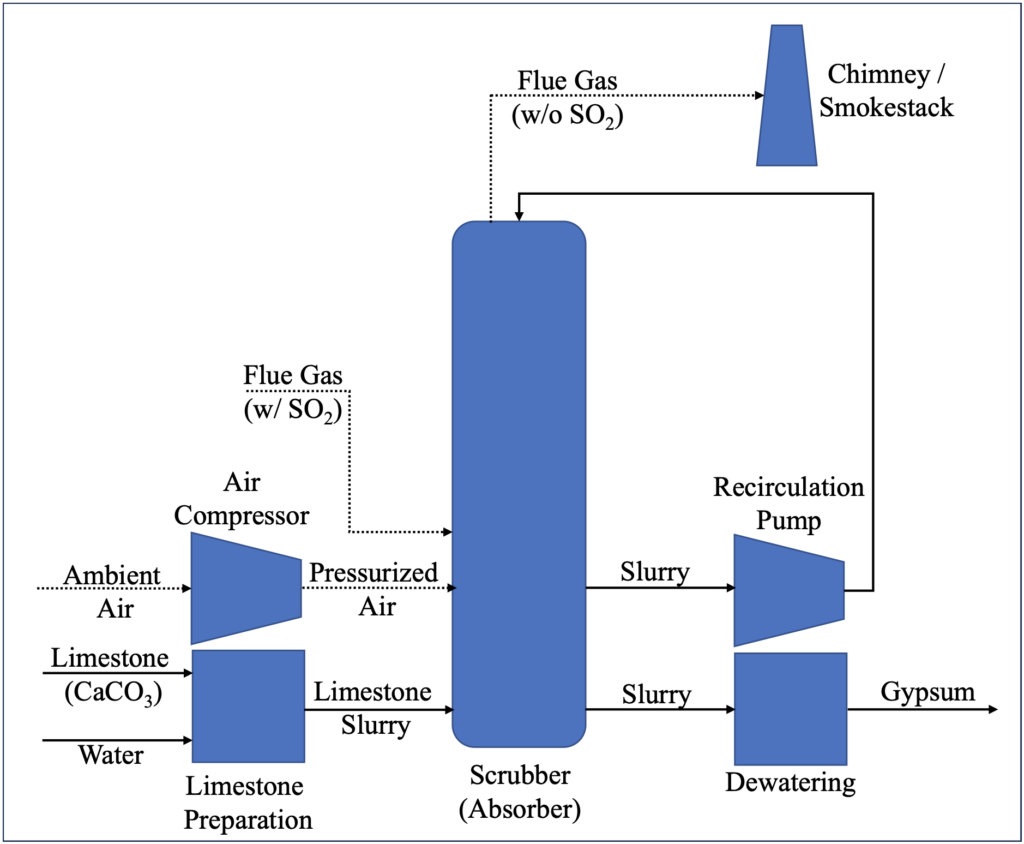
Figure 1 below is a simplified process flow diagram for the limestone forced oxidation (LSFO) process, a typical wet FGD system. The flue gas desulfurization system is based on the absorption of SO2 from the flue gas into a limestone slurry. Captured SO2 is subsequently converted to solid gypsum, a saleable byproduct, and removed from the system. The primary unit operations utilized in the LSFO process are as follows:1,2,3
- Limestone Preparation: Limestone (CaCO3) can be delivered to site by truck or rail. The limestone is then typically crushed and/or milled, mixed with water to form a limestone slurry, and pumped to the FGD scrubber to facilitate absorption of flue gas SO2.
- Air Compression: Air is compressed for sparging into the SO2 scrubber, where the oxygen (O2) in the air is utilized to force the oxidation of captured SO2 to gypsum.
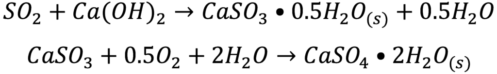
- FGD Scrubber: The incoming flue gas enters near the bottom of the scrubber (spray tower), above the liquid level, and contacts an alkaline slurry containing limestone that the recirculation pump has pumped to the top of the spray tower, providing for counter-current absorption of the SO2 (and other acid gases) from the flue gas into the slurry. Air is sparged into the bottom of the spray tower, below the liquid level, to force the oxidation of the captured SO2 to form calcium sulfate (CaSO4 • 2H2O, gypsum). Scrubbed flue gas is discharged through the plant’s stack. The overall chemical reaction is as follows:

- Gypsum Dewatering: A slurry blowdown stream is dewatered using equipment such as hydroclones and a vacuum belt filter or filter press to concentrate and remove the solid gypsum byproduct from the system. Residual liquid/slurry from the dewatering process is recycled back to the scrubber.
Figure 1: Typical Wet FGD Process Flow Diagram (LSFO)
Typical Semi-Dry FGD Process
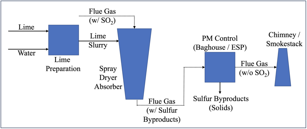
Figure 2 below is a simplified process flow diagram for a spray dryer absorber (SDA) process, a typical semi-dry FGD system. The system is based on absorption of SO2 from the flue gas into a lime slurry. The plant’s particulate matter (PM) control device subsequently removes captured SO2 from the system as a solid byproduct. The primary unit operations utilized in the SDA process are as follows:4,5,6,7
- Lime Preparation: Lime can be delivered to site either by truck or rail as quick lime (CaO) or as hydrated lime (Ca(OH2)). The lime is then mixed with water to form a lime slurry, which is pumped to the SDA to facilitate absorption of SO2. In the case of quick lime, combining the reagent with water slakes the quick lime to hydrated lime via an exothermic reaction as follows:

- Spray Dryer Absorber: The lime slurry is typically dispersed into fine droplets using a rotary atomizer and contacts the flue gas to facilitate the absorption of SO2 and other acid gases. The water in the sorbent slurry completely evaporates into the flue gas, forming a solid waste product containing the captured SO2. The SO2 is captured primarily as calcium sulfite (CaSO3), but the oxygen (O2) in the flue gas oxidizes a portion of the calcium sulfite to calcium sulfate (CaSO4). The power plant’s particulate matter (PM) collection device then captures the solid byproducts and any unspent lime downstream of the SDA. In some cases, collected solids are recycled to the SDA to increase efficiency. The primary chemical reactions are as follows:
- PM Control: The plant’s PM control device, nominally installed to mitigate fly ash (residual coal ash) emissions, is typically either a fabric filter (baghouse) or electrostatic precipitator (ESP). As the names imply, baghouses trap PM through filtration, while ESPs trap PM by applying an electric charge to attract particles to parallel metal plates. The PM control device collects the solid FGD byproducts and unspent lime, along with the fly ash, for disposal. Scrubbed flue gas is discharged through the plant’s stack.
Figure 2: Typical Semi-Dry FGD Process Flow Diagram (SDA)
Typical Dry FGD Process
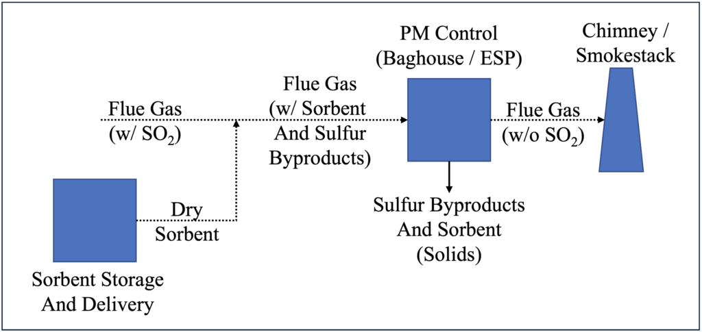
Figure 3 below is a simplified process flow diagram for a dry sorbent injection (DSI) process, a typical dry FGD system. The system is based on absorption of SO2 from the flue gas by a dry (solid) calcium- or sodium-based sorbent. The plant’s particulate matter (PM) control device subsequently removes captured SO2 from the system as a solid byproduct. The primary unit operations utilized in the DSI process are as follows:8,9
- Sorbent Storage and Delivery: High SO2 removal efficiency applications typically require a sodium-based sorbent such as trona, a mineral containing one part sodium carbonate (Na2CO3), one part sodium bicarbonate (NaHCO3), and two parts water (H2O). The dry sorbent is stored in a silo and pneumatically injected into the flue gas upstream of the PM control device. In sodium-based systems, the SO2 is captured primarily as solid sodium sulfate (Na2SO4), which the power plant’s PM collection device then removes from the flue gas downstream of the DSI injection point. The overall chemical reaction for a DSI system utilizing trona is as follows:

- PM Control: The PM control device, typically either a baghouse or ESP as described above, collects the solid FGD byproducts and unspent sorbent, along with the fly ash, for disposal. Scrubbed flue gas is discharged through the plant’s stack.
Figure 3: Typical Dry FGD Process Flow Diagram (DSI)
1 “Air Pollution Control Technology Fact Sheet: FGD – Wet, Spray Dry, and Dry Scrubbers,” U.S. Environmental Protection Agency (EPA), EPA-452/F-03-034, 2003. Retrieved on June 10, 2024. https://www3.epa.gov/ttncatc1/dir1/ffdg.pdf.
2 “Wet Flue Gas Desulfurization Technology Evaluation,” Sargent & Lundy, January 2003. Retrieved on July 24, 2024. https://www.lime.org/documents/uses_of_lime/wet_fgdte2003.pdf.
3 “Flue Gas Desulphuriser Explained,” saVRee. Retrieved on July 17, 2024. https://www.savree.com/en/encyclopedia/flue-gas-desulphuriser.
4 “Flue Gas Desulfurization,” National Lime Association. Retrieved on July 17, 2024. https://www.lime.org/lime-basics/uses-of-lime/enviromental/flue-gas-desulfurization/.
5 “Spray Dry Flue Gas Desulfurization Systems,” Babcock & Wilcox, 2021. Retrieved on July 22, 2024. https://www.babcock.com/assets/PDF-Downloads/Emissions-Control/E101-3178-Dry-FGD-Babcock-Wilcox.pdf.
6 “Air Pollution Control Technology.”
7 “Flue Gas Desulfurization Technology Evaluation: Dry Lime vs. Wet Limestone FGD,” Sargent & Lundy, March 2007. Retrieved on July 31, 2024. https://www.lime.org/documents/uses_of_lime/FGDTechEvalDryLimevWetLimestoneFGD11311001.pdf.
8 “Air Pollution Control Technology.”
9 “IPM Model – Updates to Cost and Performance for APC Technologies: Dry Sorbent Injection for SO2/HCl Control Cost Development Methodology,” Sargent & Lundy, 2017. Retrieved July 18, 2024. https://www.epa.gov/system/files/documents/2021-09/attachment_5-5_dsi_cost_development_methodology.pdf.
ADDITIONAL RESOURCES

Blog
Discover industry insights on construction disputes and claims, project management, risk analysis, and more.
MORE

Articles
Articles by our engineering and construction claims experts cover topics ranging from acceleration to why claims occur.
MORE

Publications
We are committed to sharing industry knowledge through publication of our books and presentations.
MORE
RECOMMENDED READS
Flue Gas Desulfurization: Industry and Market Overview
This post provides overviews of sulfur dioxide pollution and emissions regulations, the FGD industry, and global FGD market trends.
READ
Onshore Wind Turbine Basics: Parts, Power Generation, and More
This post on wind power basics and the components of wind turbines and wind farms is the first in a series about onshore wind energy.
READ
Carbon Capture – A Capital-Intensive Technology with Large Growth Potential
This is the first post in a six-part series that discusses carbon capture, utilization, and sequestration.
READ