August 5, 2024
Flue Gas Desulfurization: Technology Overview
Introduction to the Flue Gas Desulfurization Series
This blog post is the second in a three-part series that discusses flue gas desulfurization (FGD). The first post provides overviews of sulfur dioxide pollution (SO2) and emissions regulations, the FGD industry, and global FGD market trends. The second post provides high-level overviews of wet, semi-dry, and dry FGD technologies with respect to SO2 capture applications at coal-fired power plants. The final post explores representative FGD process flows and chemistry for each of the three FGD technology types as applied to coal-fired power plant applications.
Wet FGD Vs. Semi-Dry Vs. Dry FGD: Understanding Flue Gas Desulfurization Technology
Wet FGD Systems
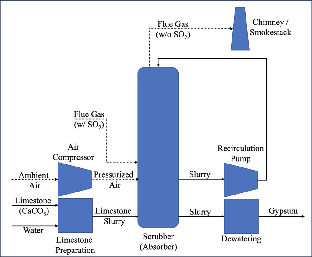
Wet FGD systems utilize a scrubber, or spray tower, to contact an aqueous slurry of alkaline sorbent (typically calcium-based reagents such as limestone or lime) with the flue gas to absorb acid gases including SO2. Captured SO2 is typically removed from the system as calcium sulfate (gypsum), which can be sold commercially, utilizing filtration processes. Wet FGD systems exhibit SO2 capture efficiencies on the order of 90% to 98%.1
Wet FGD systems comprise reagent preparation and delivery, absorber, and solids handling/filtration equipment and are generally more complicated than semi-dry and dry FGD systems. With respect to operating costs, limestone is usually readily available and relatively inexpensive,2 and reagent stoichiometry is close to 1:1 (i.e., one mole of calcium per one mole of sulfur removal),3 although parasitic power related to sorbent pumping can be a concern. Thus, wet FGD systems generally exhibit higher capital expenses (CapEx) but lower operating expenses (OpEx) than other FGD technology types4 and are therefore well suited for higher-sulfur applications at sites with significant anticipated remaining plant life.
Because contact with the liquid sorbent cools flue gas to its saturation point, downstream corrosion of the ductwork/chimney is a concern, and the stack plume may be visible (i.e., wet stack), raising concerns regarding aesthetics. Some plants opt to employ flue gas reheat strategies to mitigate the wet stack concerns.5 Additionally, based on the system water balance, a liquid discharge (i.e., blowdown) may be required, which can introduce wastewater disposal and/or treatment concerns.6,7
Figure 1 below shows a typical wet FGD process flow diagram (PFD). A future blog post will explore the technical details of the process.
Figure 1: Typical Wet FGD Process Flow Diagram

Semi-Dry FGD Systems
Semi-dry FGD systems utilize a spray dryer absorber (SDA) to contact the flue gas with an aqueous slurry, similar to wet FGD systems, but the slurry has a higher sorbent concentration and finer spray droplets than wet systems. SO2 is captured as a solid byproduct and removed from the system. Although various calcium- and sodium-based sorbents can be utilized, lime is typically employed because it is more reactive than limestone and less expensive than sodium-based reagents.8 Semi-dry FGD systems exhibit slightly lower SO2 capture efficiency than wet FGD systems, typically on the order of 80% to 95%.9,10
Semi-dry FGD systems require less equipment than wet FGD systems, typically just lime preparation equipment and the spray dryer vessel, although the design of the plant’s PM control unit will need to account for the additional solids loading due to the FGD byproduct (and for retrofit FGD projects, a re-design of the existing PM control equipment may be required). Reagent stoichiometry is generally higher than in wet FGD, potentially as high as 1.4 to 1.6 mols of calcium per mol of SO2 at the SDA inlet, depending on the application (higher sulfur-loading applications require higher stoichiometries), with lime being more expensive than the limestone typically employed in wet FGD.11 However, power requirements are typically lower than wet FGD systems.12 Thus, semi-dry FGD systems exhibit lower CapEx but potentially higher OpEx than wet FGD systems.
Because the flue gas does not cool all the way to its saturation point, wet stack concerns such as downstream corrosion and visible plume are mitigated. Further, because the water in the sorbent slurry is completely evaporated in the SDA, semi-dry FGD systems are inherently zero-liquid discharge (ZLD), alleviating wastewater disposal and/or treatment concerns.13
Figure 2 below shows a typical semi-dry FGD PFD. A future blog post will explore the technical details of the process.
Figure 2: Typical Semi-Dry FGD Process Flow Diagram

Dry FGD Systems
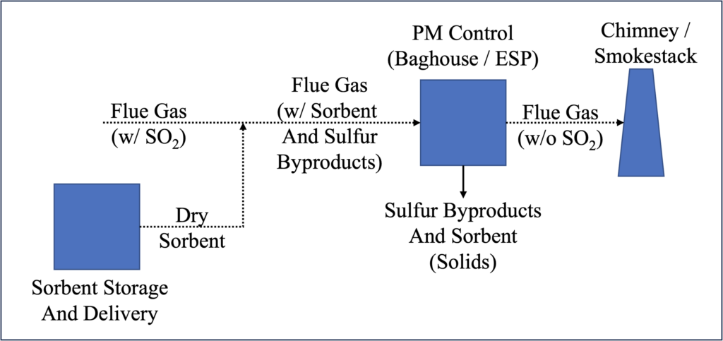
Dry FGD systems inject powdered sorbent, typically calcium- and sodium-based alkaline reagents, directly into the furnace, the economizer, or downstream ductwork to absorb SO2 and other acid gases.14 SO2 is captured as a solid byproduct and removed from the system. Dry FGD systems exhibit a wide range of SO2 capture efficiencies based on the combination of the sorbent, injection point, and PM collection device, and can exhibit SO2 removal efficiencies as high as 90%.15
Dry FGD systems require a relatively small amount of equipment compared to wet and semi-dry systems, typically just the reagent storage, delivery, and injection systems. Similar to semi-dry systems, the design of the PM control unit may need to be revised to account for the additional solids loading. Reagent stoichiometry is higher than wet or semi-dry FGD, as high as 3 mols of sorbent per mol of SO2 in the flue gas for high SO2 removal efficiency applications.16 Further, for high SO2 removal efficiencies, a sodium-based sorbent such as trona (a mineral containing sodium carbonate and sodium bicarbonate), which is more expensive than lime or limestone, is typically required.17 Thus, dry FGD systems exhibit lower CapEx but higher OpEx when compared to wet and semi-dry FGD systems and are therefore better suited for lower-sulfur applications or at sites with limited anticipated remaining plant life.
Because no water is introduced into the system in dry FGD, wet stack concerns do not exist. Further, the dry FGD system is inherently ZLD.
Figure 3 below shows a typical dry FGD PFD. A future blog post will explore the technical details of the process.
Figure 3: Typical Dry FGD Process Flow Diagram

1 “Air Pollution Control Technology Fact Sheet: FGD – Wet, Spray Dry, and Dry Scrubbers,” U.S. Environmental Protection Agency (EPA), EPA-452/F-03-034, 2003. Retrieved on June 10, 2024. https://www3.epa.gov/ttncatc1/dir1/ffdg.pdf.
2 “Flue Gas Desulphuriser Explained,” saVRee, retrieved on July 17, 2024. https://www.savree.com/en/encyclopedia/flue-gas-desulphuriser.
3 “Wet Flue Gas Desulfurization Technology Evaluation,” Sargent & Lundy, January 2003. Retrieved on July 24, 2024. https://www.lime.org/documents/uses_of_lime/wet_fgdte2003.pdf.
4 “What is the Difference between Wet FGD and Dry FGD Systems,” Ruichang, July 26, 2023. Retrieved on July 22, 2024. https://burnertec.com/difference-between-wet-fgd-and-dry-fgd-systems/.
5 “Air Pollution Control Technology.”
6 “What is the Difference.”
7 “The Flue Gas Desulfurization Process,” Micronics Engineered Filtration Group, retrieved on July 17, 2024. https://www.micronicsinc.com/filtration-news/flue-gas-desulfurization/.
8 “Air Pollution Control Technology.”
9 “Air Pollution Control Technology.”
10 “Spray Dry Flue Gas Desulfurization Systems,” Babcock and Wilcox, 2021. Retrieved on July 22, 2024. https://www.babcock.com/assets/PDF-Downloads/Emissions-Control/E101-3178-Dry-FGD-Babcock-Wilcox.pdf.
11 “Flue Gas Desulfurization Technology Evaluation: Dry Lime vs. Wet Limestone FGD,” Sargent & Lundy, March 2007. Retrieved on July 31, 2024. https://www.lime.org/documents/uses_of_lime/FGDTechEvalDryLimevWetLimestoneFGD11311001.pdf.
12 “Flue Gas Desulfurization Technology Evaluation: Dry Lime.”
13 “Flue Gas Desulfurization Technology Evaluation: Dry Lime.”
14 “Air Pollution Control Technology.”
15 “IPM Model – Updates to Cost and Performance for APC Technologies: Dry Sorbent Injection for SO2/HCl Control Cost Development Methodology,” Sargent & Lundy, 2017. Retrieved July 18, 2024. https://www.epa.gov/system/files/documents/2021-09/attachment_5-5_dsi_cost_development_methodology.pdf.
16 “IPM Model – Updates.”
17 “IPM Model – Updates.”
ADDITIONAL RESOURCES

Blog
Discover industry insights on construction disputes and claims, project management, risk analysis, and more.
MORE

Articles
Articles by our engineering and construction claims experts cover topics ranging from acceleration to why claims occur.
MORE

Publications
We are committed to sharing industry knowledge through publication of our books and presentations.
MORE
RECOMMENDED READS
Flue Gas Desulfurization: Industry and Market Overview
This post provides overviews of sulfur dioxide pollution and emissions regulations, the FGD industry, and global FGD market trends.
READ
Onshore Wind Turbine Basics: Parts, Power Generation, and More
This post on wind power basics and the components of wind turbines and wind farms is the first in a series about onshore wind energy.
READ
Carbon Capture – A Capital-Intensive Technology with Large Growth Potential
This is the first post in a six-part series that discusses carbon capture, utilization, and sequestration.
READ

